 |
 |
 |
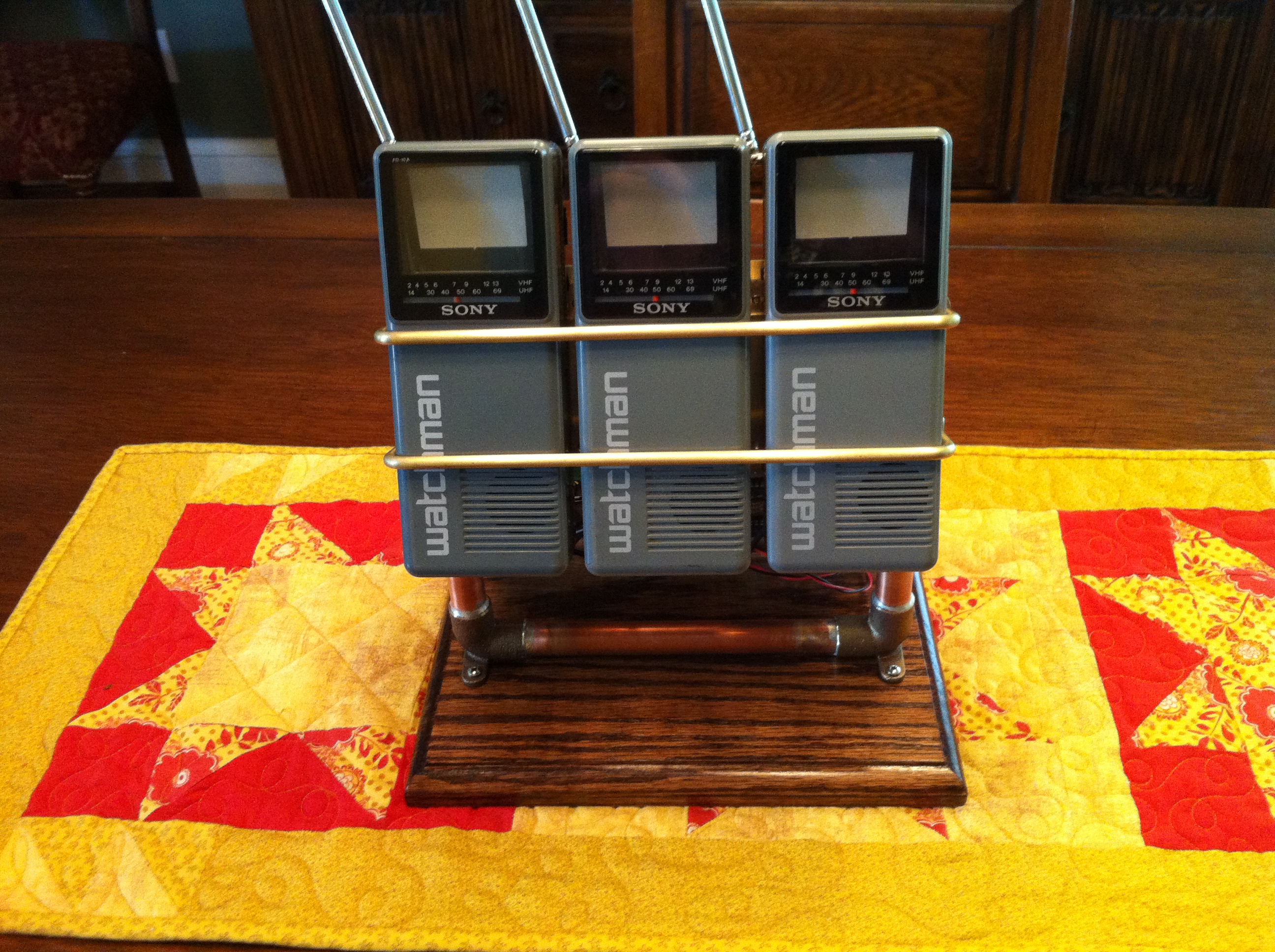
What do you do with a handful of 30 year old Micro Chips and three micro TVs? You build a clock, of course! Well, not everything is quite 30 years old. To pack this clock into a reasonable amount of space, and not consume a ton of power, a "few" modern components were thrown in. The main processor, software, and video displays are true to the state of art.
| |
|
|
 |
This project began with my desire to build and play with a part of computer history that I skipped: CP/M. In the early 1970's I designed and built my own computer, based upon the Intel 8008. My 8008 was operated by entering programs into memory from the paddle switches on the front panel. I did write a small monitor program that would communicate with an ASCII keyboard and TV display, but that was about the extent of what I did. During the three years I spent wire wrapping and soldering my 8008, more functional computers were becoming commercially available at reasonable prices.
Being newly married and strapped for cash the next computer I bought was a Sinclair ZX81 in kit form. The ZX81 was a pretty cool little computer that natively ran BASIC, but had no operating system. BASIC was a no brainer for me after spending hundreds of hours up at the University of Utah playing with the Univac 1108 during my high school days. Amazingly enough I found a company that sold a floppy disk controller that could be connected to the ZX81. I bought one and had dual floppy drives on my little ZX81! By the time I had learned just about everything I could by tinkering and programming the ZX81, the IBM PC had emerged.
My first step into the "PC" world was when I acquired an AT&T 6300 running MS DOS. From my humble beginnings with the 8008 the 6300 seems like a supercomputer! For the price of four hundred dollars, I added a 10 Megabyte hardcard. Back then 10 Megs could just about hold all the PC software that I could get my hands on. I also jumped off BASIC and started playing with Borland Turbo C.
Over the past few years, I've wanted to build a little computer around either an 8080 or a Z80. At the time I built my 8008 the Intel 8080 was a several hundred dollar chip. Building around the 8008 was cheaper, but it ultimately limited my software options so I never crossed the bridge into CP/M land. Fortunately for me 8080's and Z80's are still abundant as well as CP/M and application software.
 |
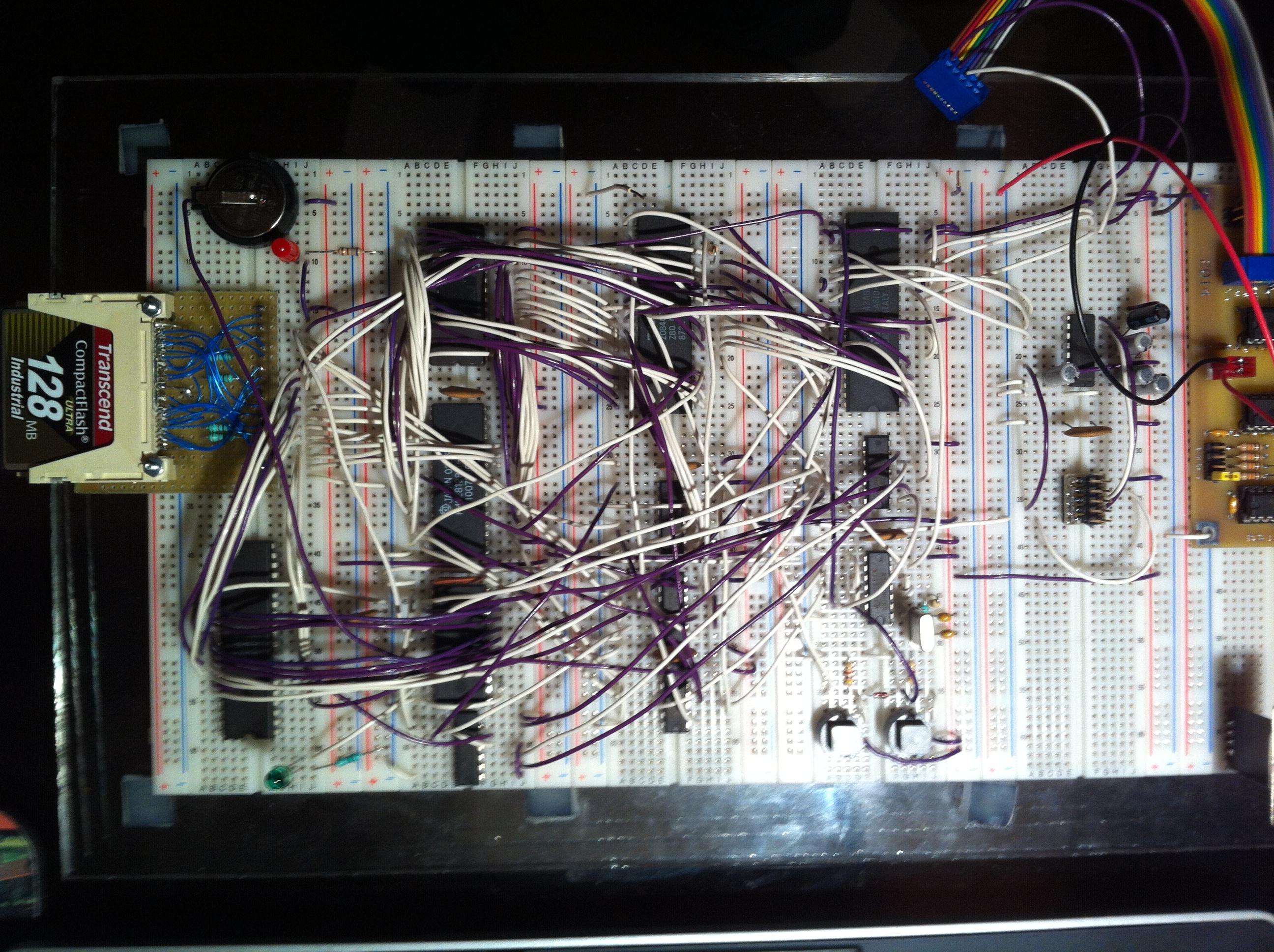 |
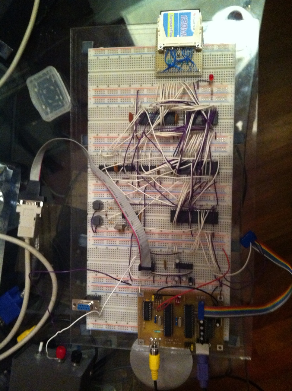
In my search for a simple CP/M project I found a lot of really great options. The simplest and most complete was a Z80 designed by Grant Searle, "CP/M on a breadboard." His project only uses 9 chips to create a complete operational computer! Grant did an amazing job documenting his project. The really great thing about the project is that I could build the first version on my own breadboard before investing in the cost of a printed circuit board. I would also add that Grant was a true gentleman and responded to all of my questions sent by email. (Thanks Grant!)
My first steps were to get Grant's basic circuit bread boarded and working. It actually took me several attempts. On my first attempt the bread boarded computer didn't boot, I'm guessing that I had a wiring error. I pulled all the jumpers and started again. On my second attempt, I had partial success. When I connected the terminal and then pressed the space bar I would get a scrolling message and garbage to the screen. After an email to Grant I swapped out the SIO/2 chip and then tried another Z80. It appears that my original Z80 CPU didn't work well with overclocking. I substituted in a Z80B and everything magically worked! At this point I plugged in the CF card and loaded CP/M. I can assure you that if you follow his schematic and instructions to the letter you will end up with a working computer!
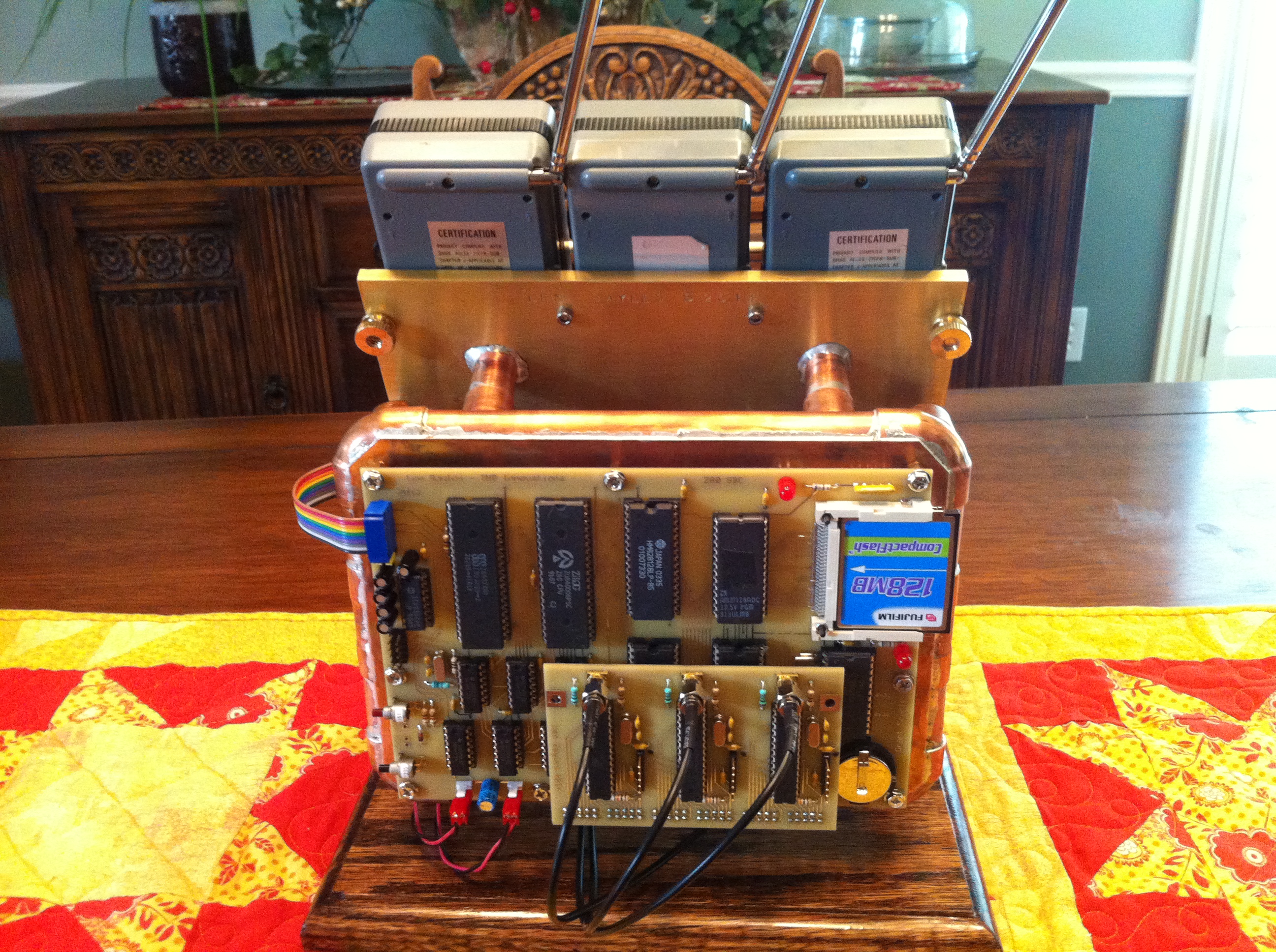
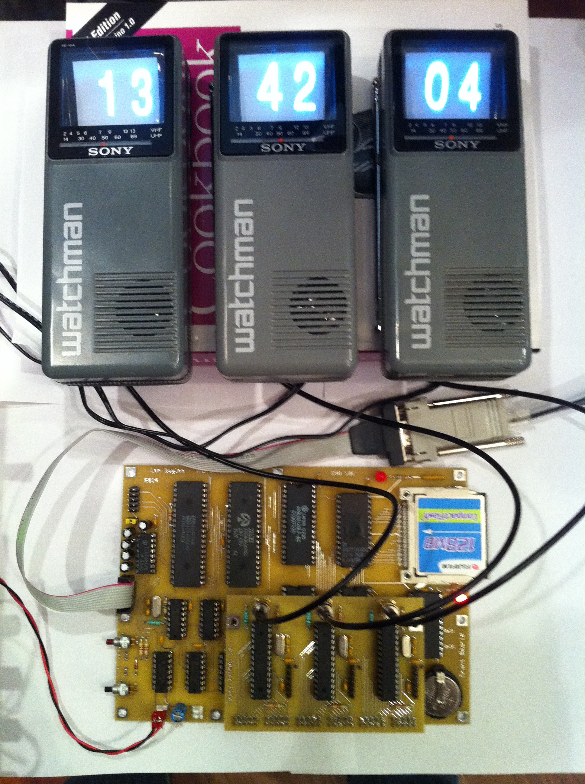
To get to my final configuration I took Grant's base design and extended the I/O by adding two 8255 Programmable Peripheral Interface (PPI) chips and a DS12885 real time clock. The two PPI's gave me 6 eight bit parallel ports that can be used as inputs or outputs. In addition to the above mentioned IC's, I added an additional two TTL chips for glue logic bringing the total chip count to 14. I think it is simply amazing considering you have a computer with 2 serial ports, 6 parallel ports, 64k of memory, and nearly 128 MB of disk storage space! When I originally constructed my 8008 I had nearly 225 IC's just for the basic computer and simple I/O. (43 for the CPU card, 23 for the PIO, and 156 for the 16k of memory.)
One specialized tool you will need to build the computer is an EPROM programmer. Looking at the schematic of Grant's Z80, you'll see IC U4 is a 27128. This chip is a 16k by 8 bit EPROM that needs to be programmed with the software necessary to boot the computer. You can find suitable programmers on EBay or Amazon, costing between $50 and $100. Before you buy the programmer, look at the programmer's documentation to make sure your chip is supported. You may also want to buy an ultraviolet chip eraser. EPROMS have a little quartz window on the top of the chip. To clear a previous program the chip needs to be exposed to ultraviolet light for 10 or 15 minutes. Most chips will come blank, but it's possible to buy "pulls" (used chips) that come in an un-erased condition. You should be able to find an eraser for under $20 on EBay or Amazon.
Grant includes detailed and accurate instructions on how to initially install CP/M on the computer. He has written a really helpful utility that converts programs needing to be transferred to the Z80 to a hex format. Once the files are converted, it is a simple cut and paste operation to transfer your files. One "gotcha" that tripped me up was failing to enable hardware flow control on Tera Term, the terminal program I ran on my Windows PC. I used the same process to upload all other software to the Z80 machine as well.
After getting CP/M installed and working I needed to get a programming environment setup to access and test the additional hardware that I had added to the computer. This meant I needed to find an editor and a compiler. CP/M 2.2 does include both an editor and an assembler if you want to go that route. ED is the supplied line oriented CP/M text editor, which took me back to my DOS days using edlin. Preferring C over assembly, and having been spoiled by modern software, I decided to look for alternatives to the built in CP/M development tools. If you are planning to download and compile my C code, you will need to at least install the Aztec C compiler.
I tried about six different editors until I ran across Express Edit which gives you full screen editing using WordStar-like commands. If you can remember about a dozen commands, you are in business. You can download the "ark'd" program from "The *HUMONGOUS* CP/M Software Archives". The file is called express11.ark in the directory linked below. The software package comes with a configuration program to help you set up the correct environment for your terminal. (ECONFIG1.COM)
Included in the distribution is a documentation file detailing use of the editor. (EXPRESS1.DOC) I extracted just enough information from the document to produce a cheat sheet of cursor controls to get me underway. It took me about 10 minutes to master the basic navigation commands to survive.
I first found and installed the MIX C compiler but moved to the Aztec C compiler. The MIX C compiler worked fine, but I was unable to find any amount of useful documentation. On the other hand, I found the full manual for Aztec C that documents all of the programs and the library functions. Aztec C includes two compilers, one for the 8080 and another that optimizes for the Z80. Building a program is a three step process.
After running these three commands, if your program complies without errors, you will find the executable file TVCLOCK.COM in your working directory.
To test the 8255 PPI's, I first wrote a very simple program that continuously counted from 0 to 255 and put the count on all six of the output ports. While the ports were actively "counting" I could check them with my logic probe to verify the activity. Before using the 8255 PPIs you need to configure the chip with one of three mode selections. The 8255 uses two address lines to access 4 unique ports on the chip. The lower three addresses are the data I/O ports. The 4th port is the configuration register. Writing 0x80 to the chip sets it to Mode 0 having three individual output ports. If you use the board for another application where you need input ports, please refer to the data sheet for the correct configuration.
8255 Data SheetWhen I was looking for an RTC I ran across the DS12885, I really liked this chip for several reasons. First, it had a simple battery backup capability. It's the same chip in most PC's, so it should continue be available. It can be setup in a BCD or binary mode, and had some other nice features. The only down side is that the DS12885 was a little tricky to interface to, as it was designed to site on an actual computer bus: either an Intel or a Motorola. The chip expects an address and data cycle more like a memory chip. In my configuration I use two distinct I/O addresses to access the chip. One I/O port is used for addressing the RTC's internal registers, and the other I/O port is used to read or write the data from the addressed register. I found a really nice write up by Wilf Rigter on how he had interfaced the same RTC on a Sinclair ZX81. Adjusting the circuit a bit for the signals I had on Grants Z80 computer, I got the RTC "ticking" along nicely.
I wrote separate programs to set the real time clock as well as reading the clock and printing the result on the command line. Once you set the time, the battery backup will keep the time accurate even when the computer is powered off. You will notice in the code I have written that a loop reads the UIP bit (Update In Progress) from control register A. When the UIP bit is set to 1 it indicates that the RTC will do an update to the time and date registers soon. If you try and read from the RTC at the same time as the update occurs it will fail to update and your time will be incorrect. I wait until the UIP bit clears to 0 which indicates that you have at least 244us to read the registers from the clock. Watching the UIP going from one to zero is also a good way to have accurate second counts to update the display. The RTC is capable of generating periodic interrupts, but I opted not to go this route to keep the hardware design simple. Considering that CP/M is a single tasking OS, there are no other programs running concurrently to mess with the clock timing.
 |
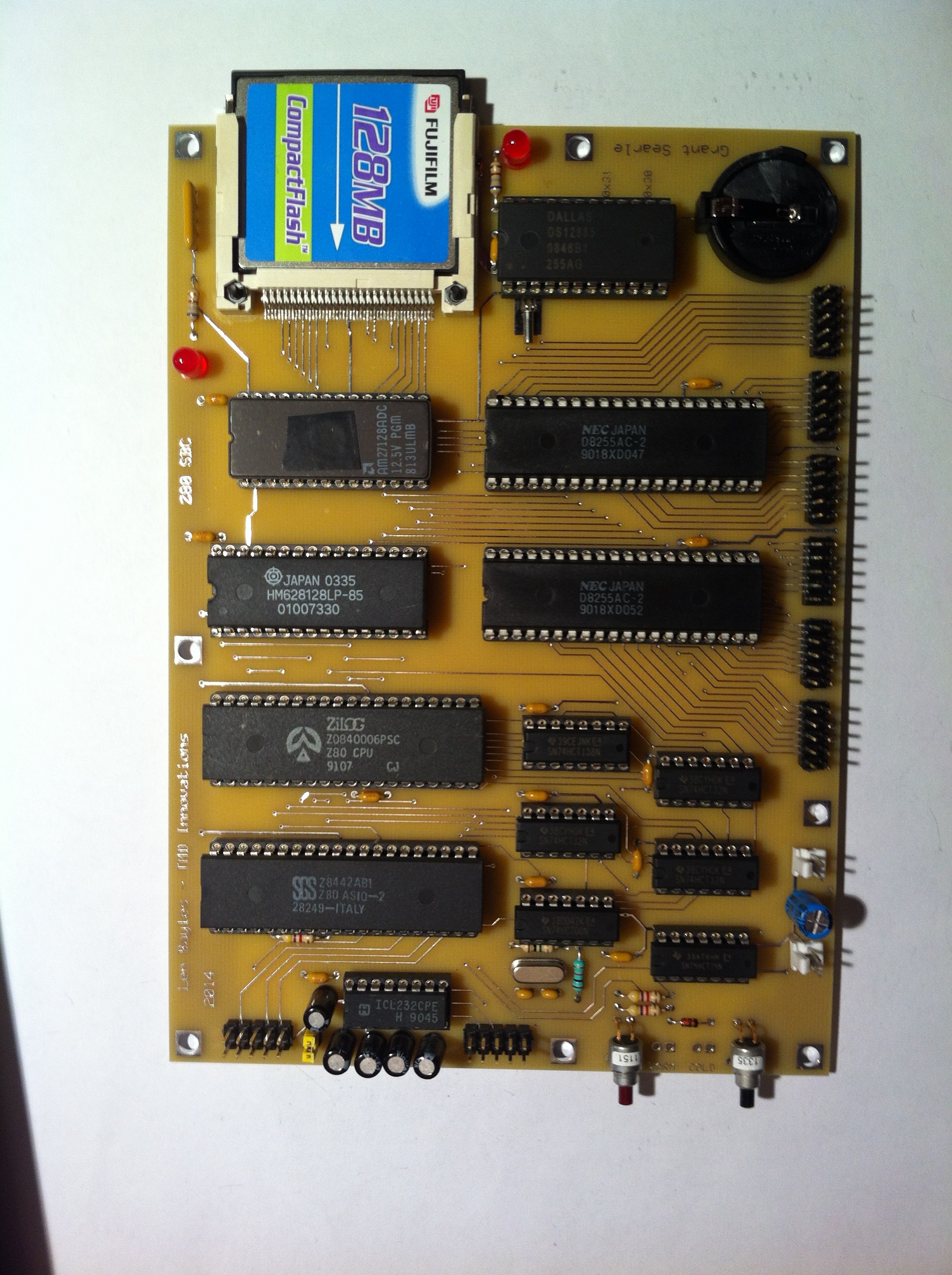 |
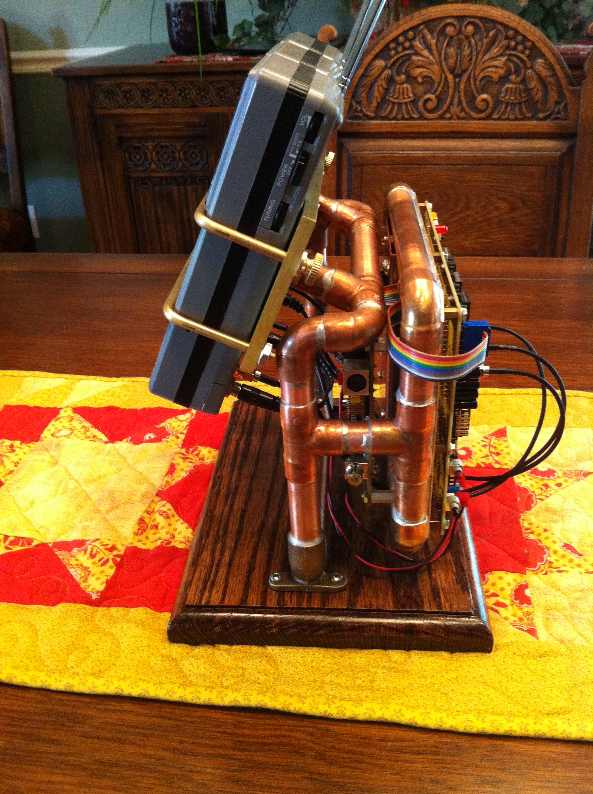
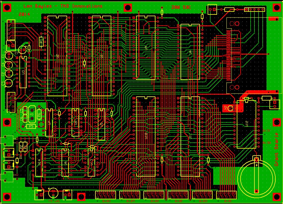
Now that I knew Grant's Z80 computer and my peripherals played nicely together, it was time to commit the project to a circuit board. I use ExpressPCB to make my circuit boards. They have free schematic and PCB design software. The boards are really high quality and reasonably priced. Once I order boards they show up within a week.
One really helpful hint in designing circuits and PCB's is to ALWAYS keep an accurate schematic. Every time you make a change to your design, document your changes, and then FOLLOW your schematic. Trust me, after decades of building projects, this one little tip will keep you from making expensive mistakes, especially when you move from a breadboard to a circuit board.
The complete board is 5 by 7 inches overall. Except for the CF socket, which I talk about in the following paragraph, I populate the board in order of part height: diodes, resistors, smaller caps, ic sockets, other parts, and then the connectors. The reason I do this, is so I can lay the board on my desk and have the parts fully seated against the board. Over the years I?ve found this method makes assembly much easier.
The only thing tricky about assembling the circuit board, is the surface mount Compact Flash socket. If you haven't ever done surface mount, don't worry; it's actually not a big deal. There are a ton of great tutorials you can watch to get an idea of how to begin. To do surface mount you need good light, magnification, fine solder, a flux pen, a very small tip on your soldering iron, a steady hand, and solder wick! Before placing the part on the circuit board, I flux the pads and then lay down a small amount of solder on one of the end pads. Next, I place the socket over the pads and align the pads carefully. Once the socket is lined up, I reheat the end pad to re-melt the solder I previously put down. If the socket is still in alignment, I solder down the pin on the opposite end. Once that is done, I go through and solder down the remaining pins. If a solder bridge happens between pins, ignore it for now and finish soldering all the remaining pins. Lastly pull out the solder wick and clean up any connections that have solder bridges, or excess solder. When you use the wick, be really careful as to NOT get the solder wick stuck to the pins. Always keep the tip of your soldering iron on the wick and remove them together. The wick will only pull solder off the top of the pins and nothing beneath the part leaving the part soldered to the traces. I "bolt" the socket to the board once I have completely soldered all the pins. Bolting the CF socket before you solder will prevent you from positioning if necessary. On my socket there were also two mounting pins on each side of the card I soldered to the PCB.
I had several ideas on how I wanted to do the display for the clock. My primary design goal was to use a display that would have been available in the 80's when both the Z80 and CP/M were in the mainstream. I've built clocks before using individual LED's, seven segment displays, nixie tubes, an oscilloscope tube, and even moving needle meters. I kicked things around a bit with my friend Albert, who I consider to be the clock guru! Using a small CRT video display quickly became the obvious conclusion. So for a few weeks I set out on an exploration to see what was still abundantly available and relatively cheap.

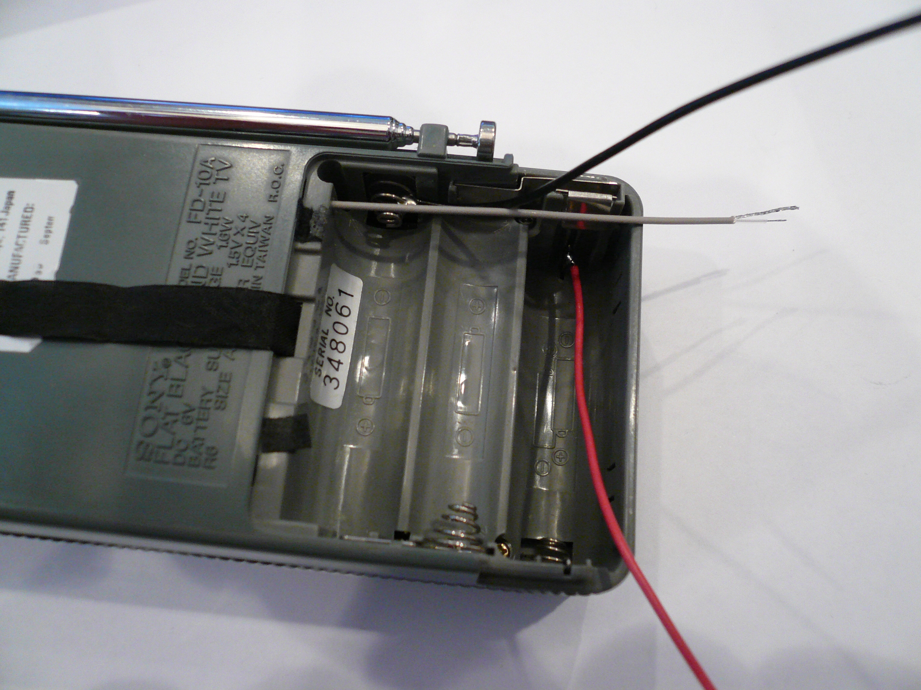
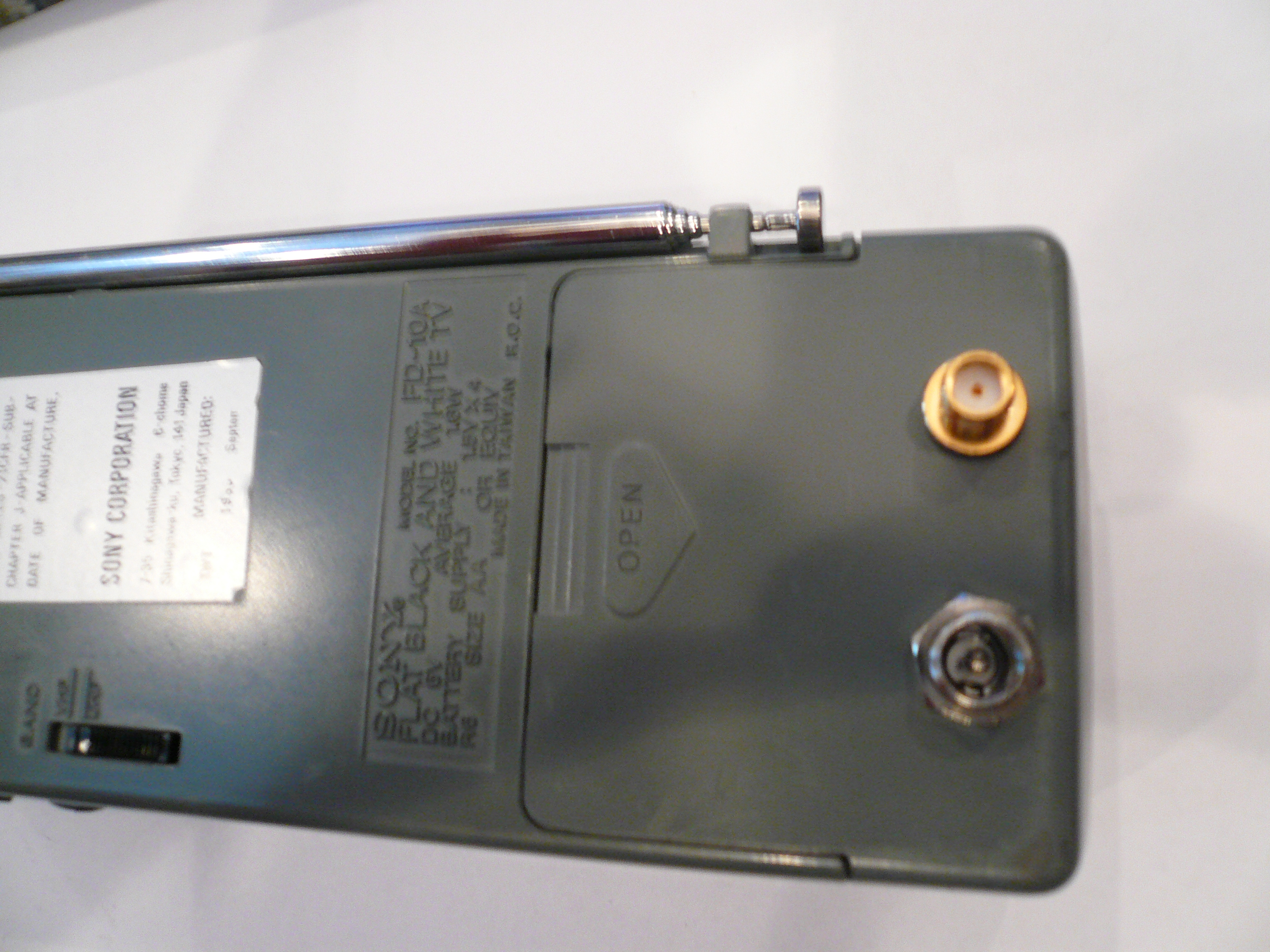
The Sony Watchman, Model FD-10A, quickly became the target of my desire for a tiny video monitor. The FD-10A boasts of a 2 inch diagonal folded cathode ray tube. Yes, a real CRT. It has a built in VHF/UHF tuner that was designed to receive the now extinct analog television broadcasts. Because they are non-functional from the broadcast TV standpoint, they fetch a pretty minimal price on Ebay. For my clock I bought four Watchman's, one came DOA, unfortunately. I paid less than $20 for each one, including shipping. Overall they looked really good for a device built and sold in the 80's.
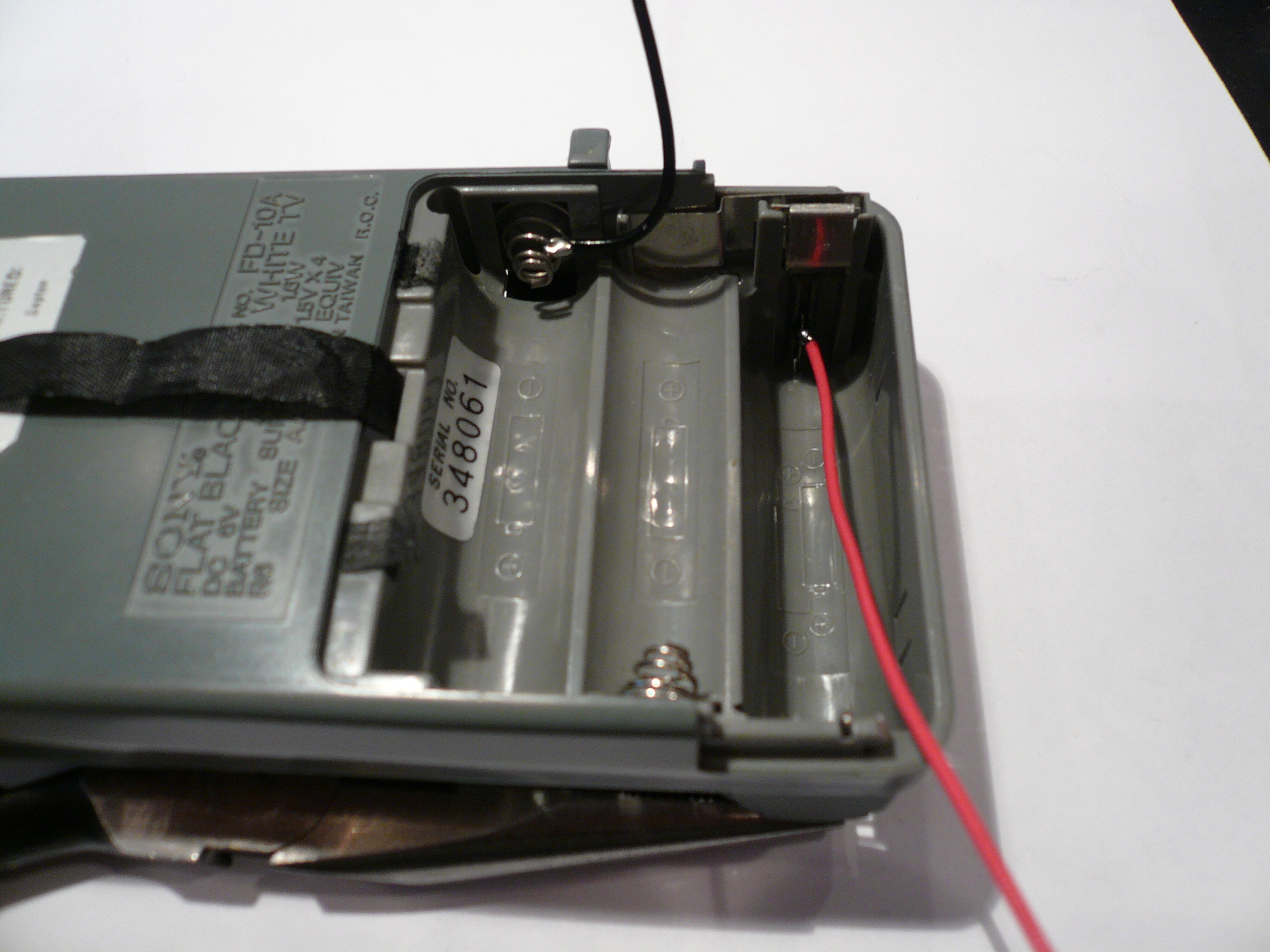
Since there is no direct video input the Watchman needs to be modified. The modification is trivial, but it does take some patience. To make the modification it is necessary to remove the back cover, locate the correct trace on the main circuit board, and then carefully cut the trace with an x acto knife. Once the trace has been cut a small piece of coax is soldered to the input side of the circuit to connect to the video driver board. I opted to run the coax through the battery compartment and install a connector to the battery compartment door, as well as a power jack.

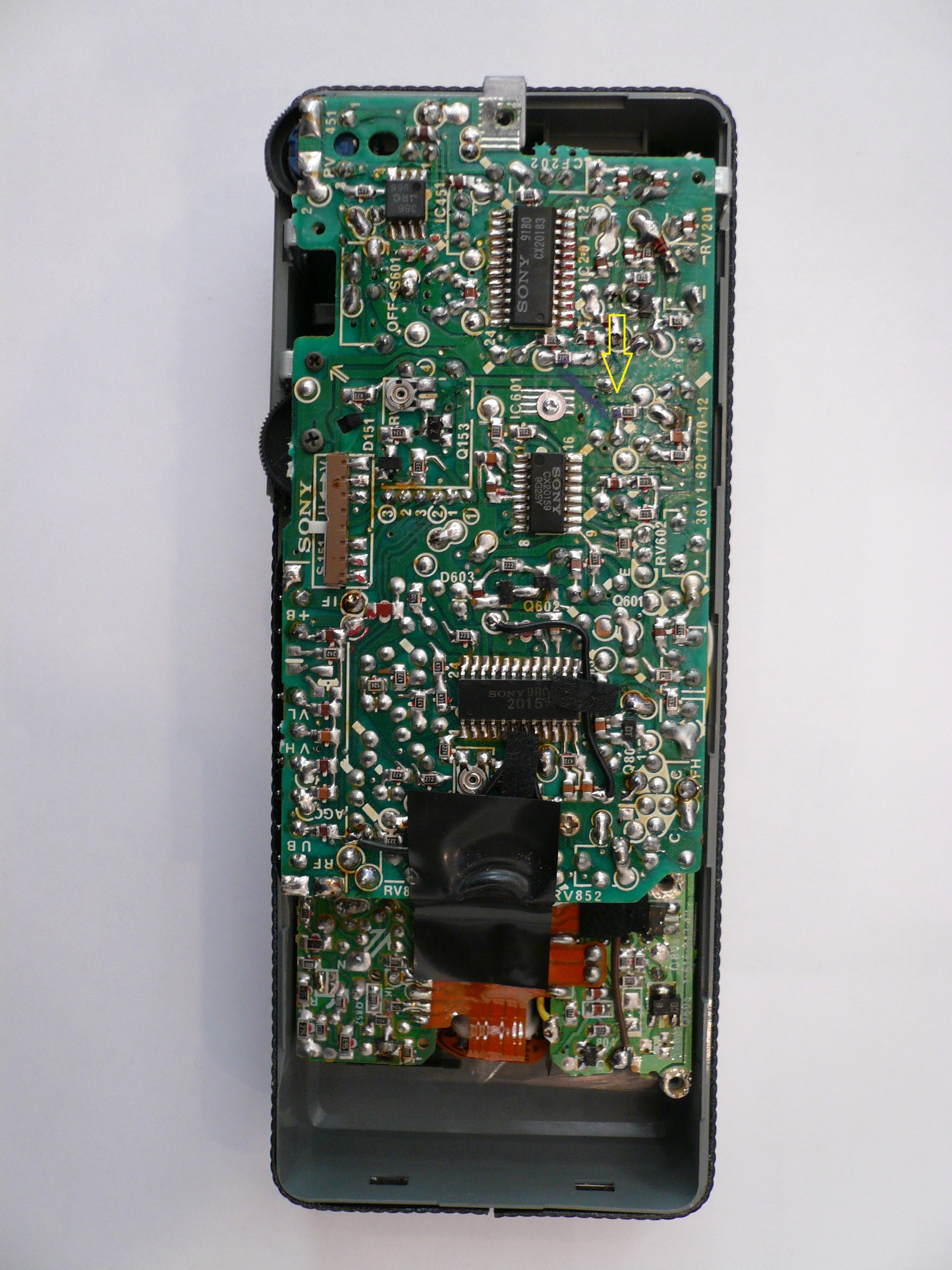
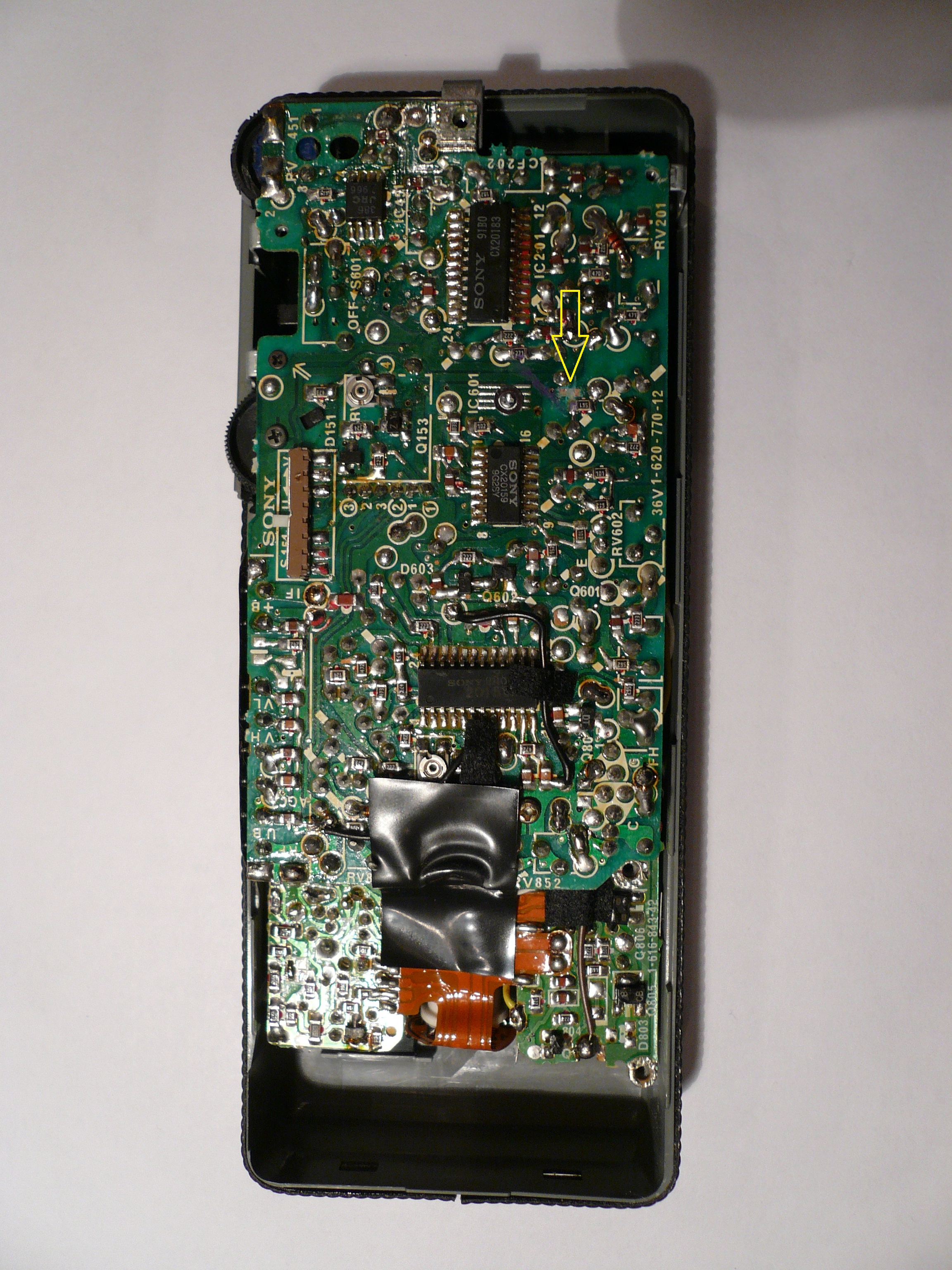
To locate where the video needed to be injected into the Watchman, took an oscilloscope and patience. I couldn't find a bit of documentation for the FD-10A. The main board has three surface mount chips soldered to it. (CX20183, CX20159, and a CX20157) I couldn?t find documentation on any of the chips either, although it is obvious where the tuner is in the TV. Working from the tuners output, it is possible to deduce which chip was the IF amplifier. Starting with the IF amp chip I carefully probed each pin on the IC until I found the NTSC video signal. I was lucky enough to still be able to receive two UHF analog stations. Without an on-air broadcast station it would have been possible to use the channel 3 output of a VCR. Once I had found the video signal, it was just a matter of tracing it to a point on the board where I could conveniently cut off the tuner signal and inject my own video signal. Once done I had my video monitors!
Click on the images for a close up view. The arrow points to the modified location.
 |
 |
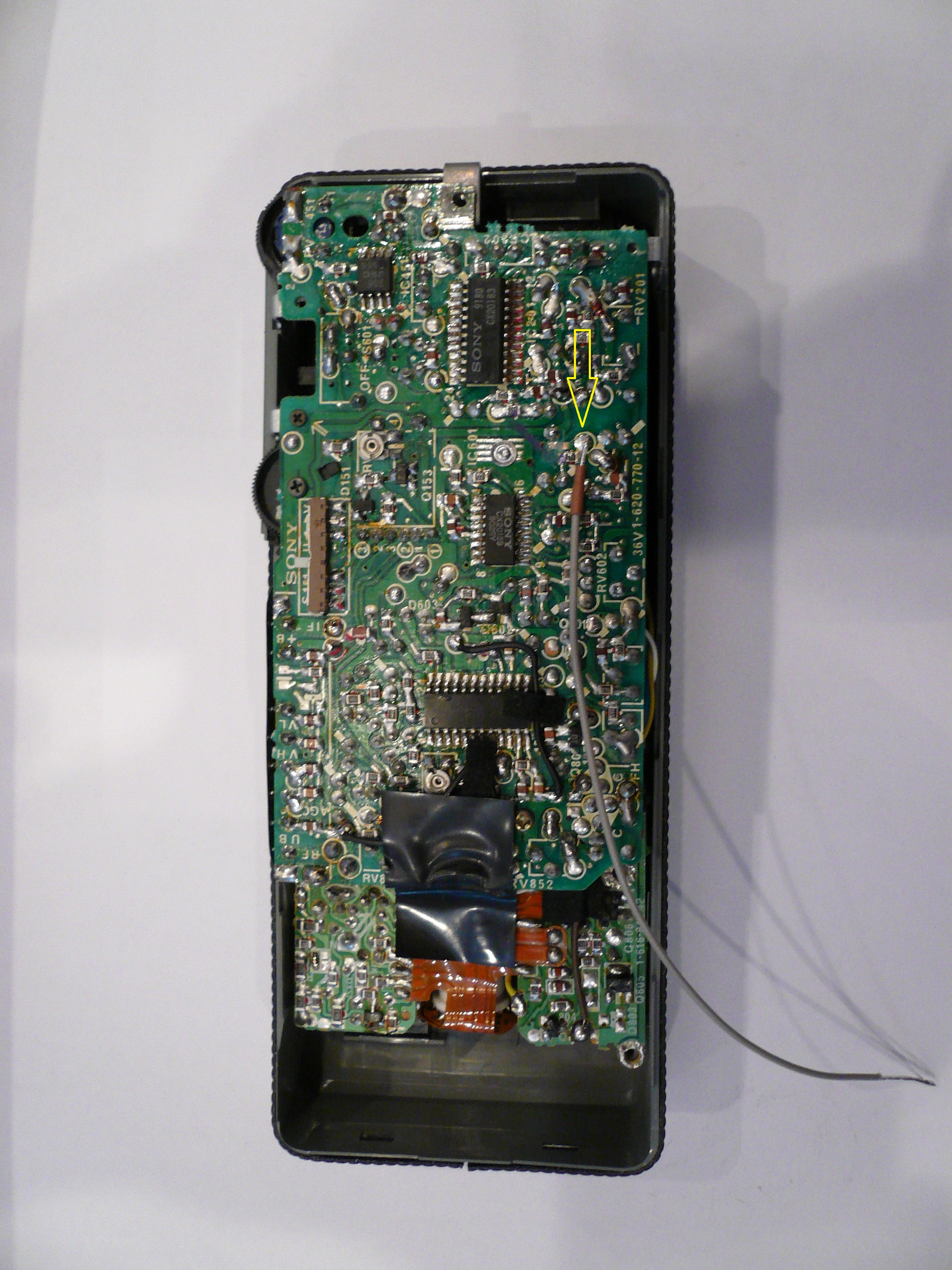 |
The coax needs to be extremely thin to allow it to fit between the main circuit board and the rear case. I had a hard time finding small enough coax until my friend Jeff pointed me to an antenna from Aloft Hobbies that was designed for remote control airplanes. The antenna is made from a piece of coax long enough to be cut up and used in the three Watchmans. Working with coax this small takes care not to cut through too many layers. The outer diameter of the coax is .045 inches. To do the stripping I used a sharp razor blade held on two shims and rotated the coax under the blade. On the end connect to the circuit board do not connect the braid, only the center conductor. The shim height to cut through the sheath and outer braid is .034 inches. To only cut through the sheath and preserve the braid I used shims that are .04 inches thick. Around the end that goes to the board I put on a piece of 3/64 heat shrink so the outer braid does not short to the board anywhere. I used a pin vice to drill a hole large enough to pass the coax into the batter compartment. From there I connect the center lead, and outer braid to a pass through SMA connector.
In addition to the SMA connector, I mounted a 2.1 coaxial power jack to the Watchman. I wrapped and soldered wires to the battery connectors and hooked them to the power jack. From the ground side of the power jack, I took a small wire and grounded the SMA connecter so the video coax would have a ground. Be really careful drilling the battery holder cover so you don?t break the plastic. I also cut and drilled a small piece of aluminum to sandwich on the back of the cover, to add strength.
 |
 |
 |
 |
 |
 |
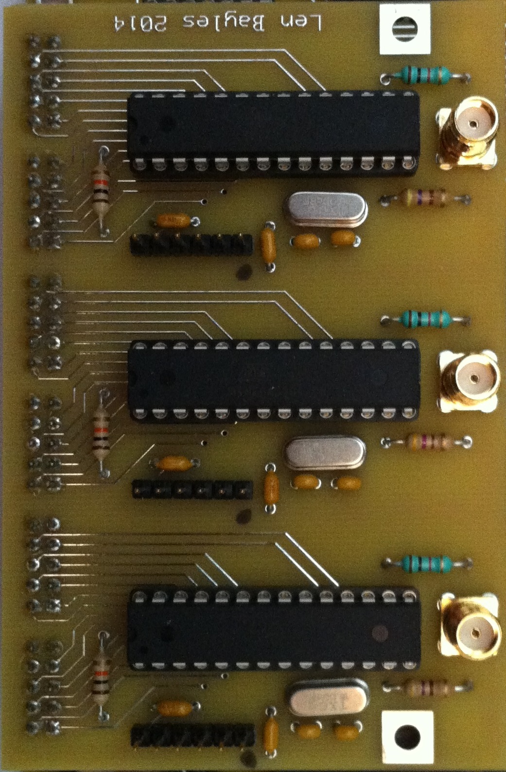 |
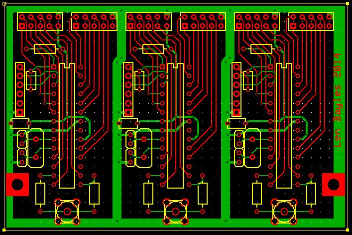
Next, I needed to design a two character video driver board that would generate the signal that goes to each of my micro-monitors. This is where modern microprocessors really get cool! The video terminal I built for my 8008 was a VERY large board which held 56 IC's. It was capable of producing a 40 character by 25 line display. The memory was comprised of shift registers. Interestingly enough, my 8008 video display used the same chipset used in the Apple I video display.
Each of the three two character video drivers are implemented using a single ATMEGA 328P processor and two resistors, that are used to mix the video and sync signals. The only other parts on the board are the 16Mhz crystals, caps, pull up resistors, and connectors. All of the real magic happens in the software. The 328P is basically an Arduino UNO loaded with Optiboot. They use the TVout library to produce a NTSC signal that can be fed directly into the Watchmans. All of the characters are displayed using bitmaps that were generated using Imagemagic. Character selection is simply done by putting the BCD digit on two input ports of the ATMEGA chip. It is also possible to select numerals or uppercase letters by their ASCII code on the ports as well. The TVout library made the implementation a cakewalk. I have to really admire the Arduino community for the vast number of usable libraries that exist.
The board containing the video driver chips has a programming header for each individual 328P processor. If you have ATMEGA chips preprogramed with optiboot you can simply plug them into the board. Then connect a FTDI Basic Breakout USB to TTL serial convertor board to upload the sketch to the chips. Make sure you verify the orientation of the header pins when connecting the adaptor. You can do this with the clock running and see your results immediately after your upload is complete.
My source files include everything you need to compile and load the sketch onto the Arduino chips. I'm including the information below if you want to create your own custom fonts.
Normally you would use the built-in characters with the TVout library. In my application, little bitty characters would be really hard to see. I only needed two very large characters that would cover the entire display. To start the process of creating bitmaps that are converted to the arrays used by the TVout library you need to create a 1 bit BMP. You can use Paint on a Windows machine, or any graphics program that is functionally equivalent. Since I needed to create 10 digits and 26 letters that appeared consistent in size, I opted to use the command line program ?convert? from Imagemagic run on a Linux box. Below is the command I used to generate the BMP for the letter A. It was a bit tricky to find the correct command to cause Convert to create a 1 bit BMP that worked with the image2code. You will know if your BMP is not correct because image2code will create an array all filled with all zero's, 0x00.
convert -background white \
        -fill black \
        -font Helvetica-Narrow \
        -monochrome \
        -size 50x90 \
        -pointsize 90 \
        -gravity center \
        label:A \
        A.bmp
In the next step of the process, you convert the BMP that you just created into a bitmap that will be included in your Arduino sketch. If you use the Windows application you simply drag and drop the BMP file onto the program and it converts the image to an array that you cut and paste into your code.
For this process, I also downloaded the code trunk that would compile under Linux and converted all the files on the command line. Here is the command I used to process the A.bmp image.
image2codecmd --orientation=horiz-msb \
                     --left2right=1 \
                     --top2bottom=1 \
                     --writer=0 \
                     --invert=1 \
                     --force8bit=0 \
                     A.bmp \
                     A.txt
More detailed instructions can be found on the links below, including the Windows program and source files that can be compiled on Linux.
 |
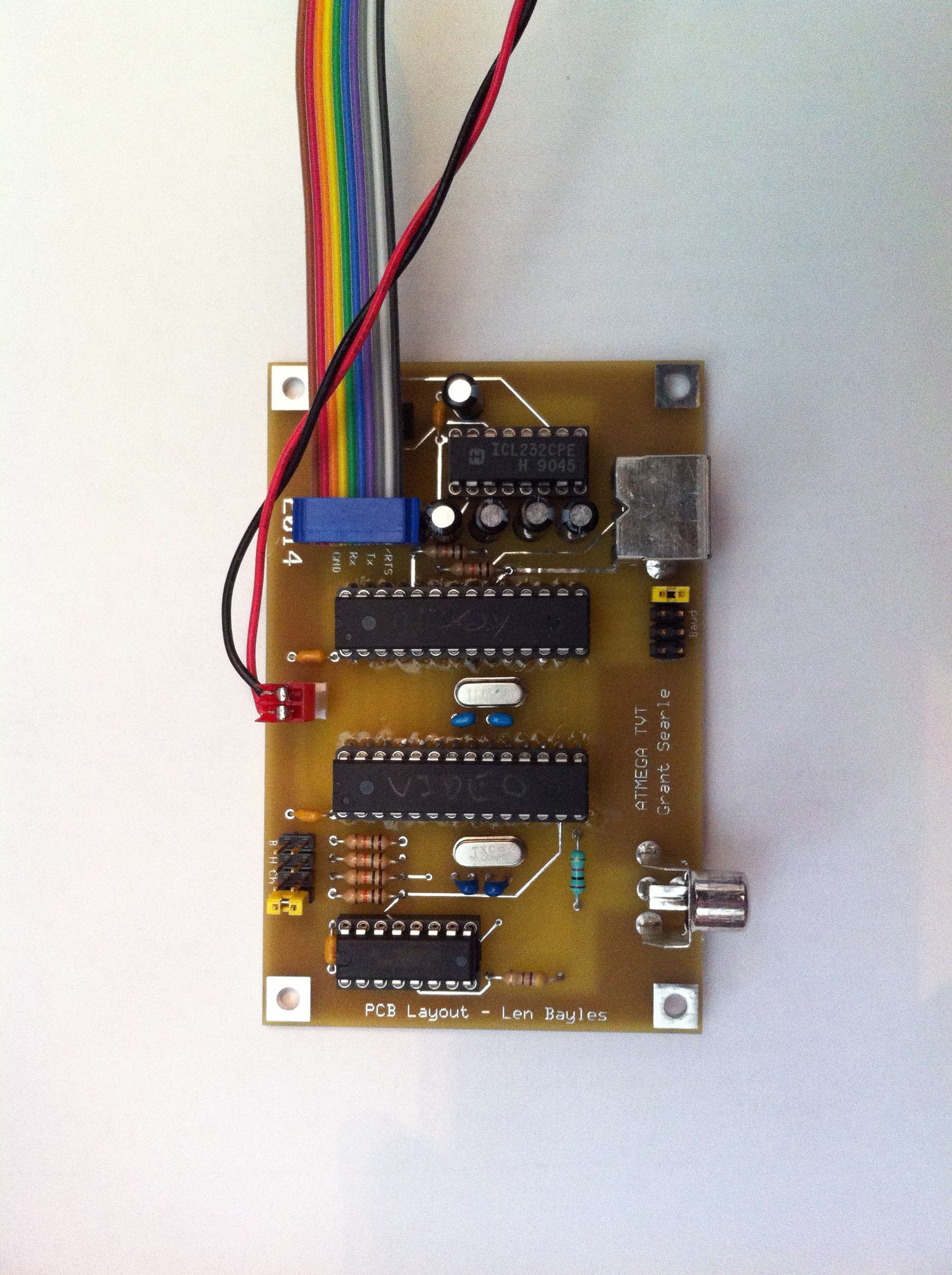 |
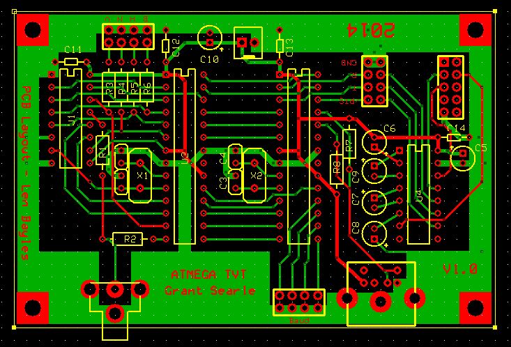
Last but not least, I want to talk about Grant's little ATMEGA serial terminal.
I actually built this project before building the Z80 computer. Just like the Z80 I bread boarded up the terminal to see if it would do what I needed before committing it to a PCB. I made a few changes from Grant's original design. My plan was to put everything on one board and use only the 8 bit transfer mode. I also wanted to have control over the baud rate without reloading the software. Not needing the other interface modes, I cannibalized the code to read 4 jumper settings to set the baud rate on boot. I also added jumpers to allow setting the 40/80 character, double height, and bold modes. Everything fits nicely on a PCB express miniboard. I set the board up to be used with the Z80 without the RS232 interface. If you want to use it in another application, simply put jumpers on the header to connect the RS232 drive chip.
| Contents of this page are Copyright by Len Bayles © 2014 | Updated May 22, 2020 |